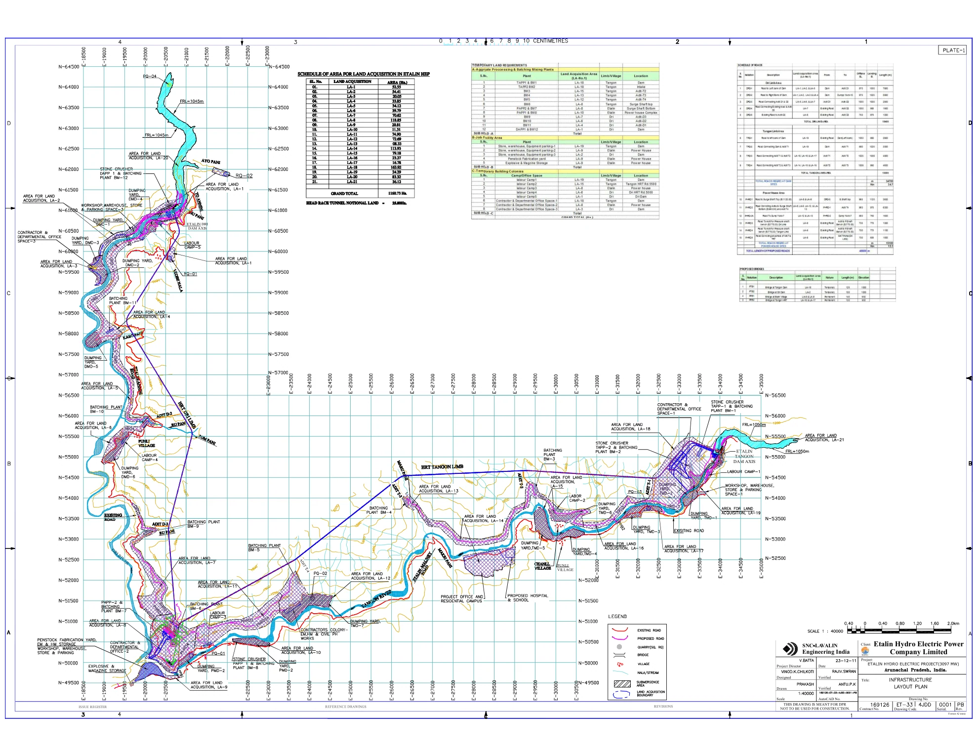
A navigable, drawing-linked site massing prototype for the Etalin scheme. It is not the finished dam model, a hydraulic simulation or an operational digital twin.
SOURCE-DERIVEDWhat the file establishes
The project title and 3,097 MW label; Dri and Tangon dam axes; the powerhouse area; HRT, surge and tailrace labels; road and bridge layouts; muck-yard sheets; and a typical retaining-wall detail.
River footprints were extracted from page 1. Asset anchors and main route centerlines were manually interpreted. Muck-yard figures are transcribed as printed.
ILLUSTRATIVEWhat is not a measured design
All terrain heights, structure masses, subsurface profiles, tunnel display thicknesses, yard volumes, building shapes and simplified road widths. The scene is not georeferenced. Terrain was not reconstructed from surveyed contours.
Dam blocks deliberately omit spillway bays, gates and generating equipment rather than invent those configurations.
Inputs required for the complete engineering-led environment
01Terrain & coordinatesCAD / GIS layouts, coordinate system and datum, terrain survey / DEM, imagery and approved boundaries.
02Both dam complexesGeneral arrangements, plans and sections; crest and foundation levels; spillways, outlets, gates, intakes and diversion structures.
03Water conductor systemsHRT / penstock plans and profiles, bore configuration, surge shafts / chambers, elevations and tailrace outlets.
04Powerhouse & plantCavern and building sections, generating units, turbine-generator geometry, cranes, transformers, electrical / switchyard layout.
05Project infrastructureValidated road / bridge profiles, muck-yard boundaries and final levels, facility layouts and approved rehabilitation plans.
06Interactive behaviourApproved operating sequences, training goals, construction schedule and hydraulic datasets where numerical simulation is requested.
Source quantities need review, not silent correction.For DMD-5 and DMD-6, the printed average length × average sectional area does not match the printed capacity. Figures remain unchanged and flagged. Page 15 reports TMD-7 and TMD-8 together; that combined capacity must not be counted twice.
No external Etalin project facts, live data feeds, regulatory status, site measurements or operational claims have been added. VR and headset controls are not implemented or tested in this version.